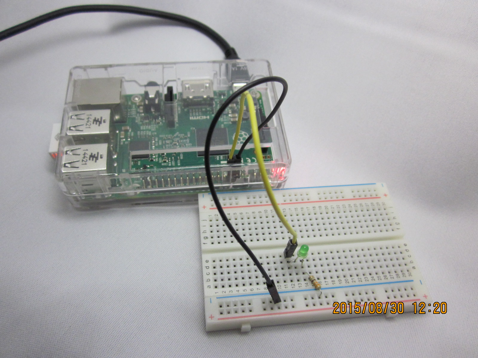
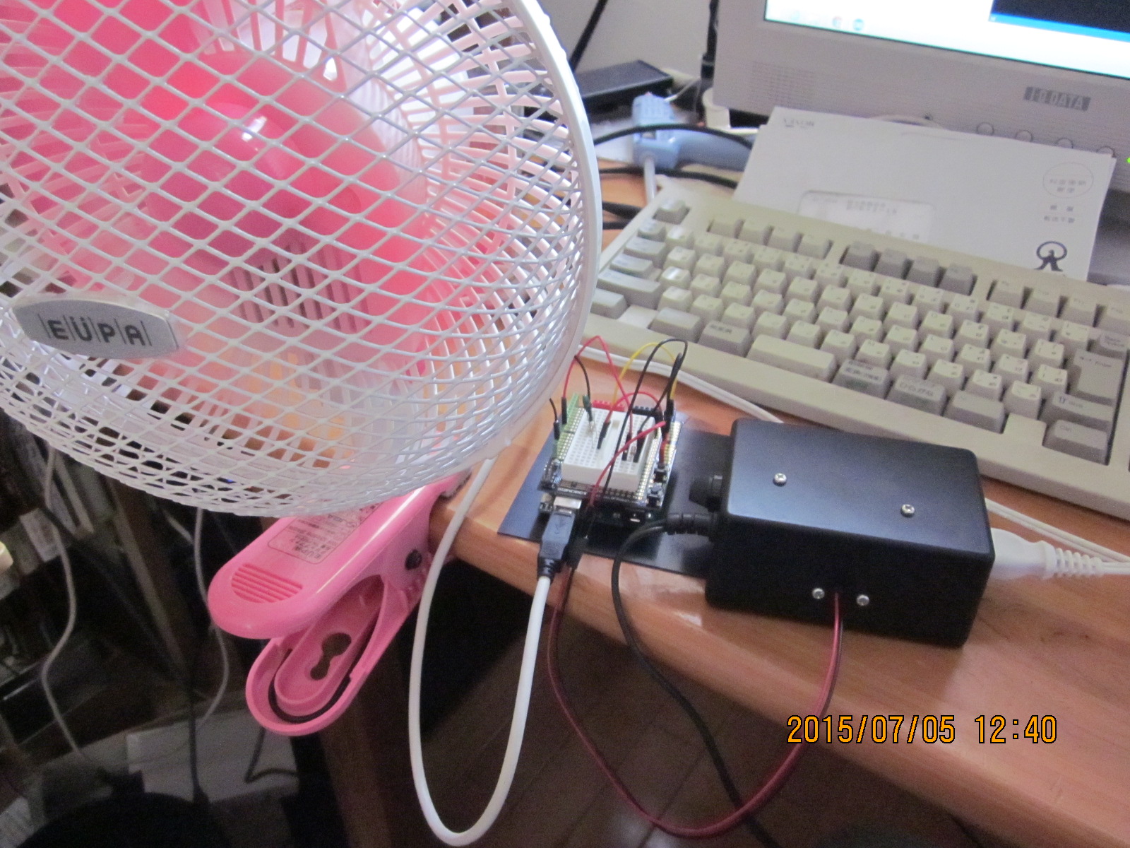
LEDを強力に光らせることが出来たので、いよいよWebサーバつき多機能リモコンを作成する。卓上などに置いておき、ネットワークにつないで、スマホなどから複数の電化製品を操作できるというものだ。
ここでは、いくつかのテクニックを使った。
一つは、フォームが大きくなってしまい、ハードコーディングするとメモリが足りなくなる。そこで、SDカード内にHTMLを置き、これを読み出すようにした。
同様に、リモコンから読み取った数値データが大きくなって、普通にハードコーディングしたのではメモリが不足する。そこで、「PROGMEM」というキーワードを使って、フラッシュメモリ内にデータを置き、これを読み出すようにした。
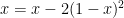
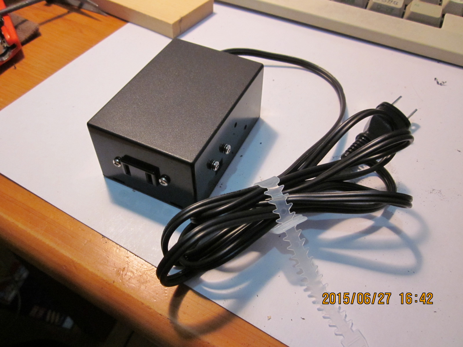
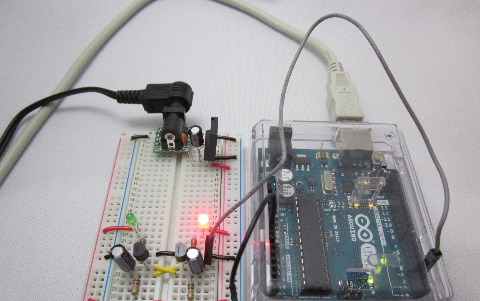
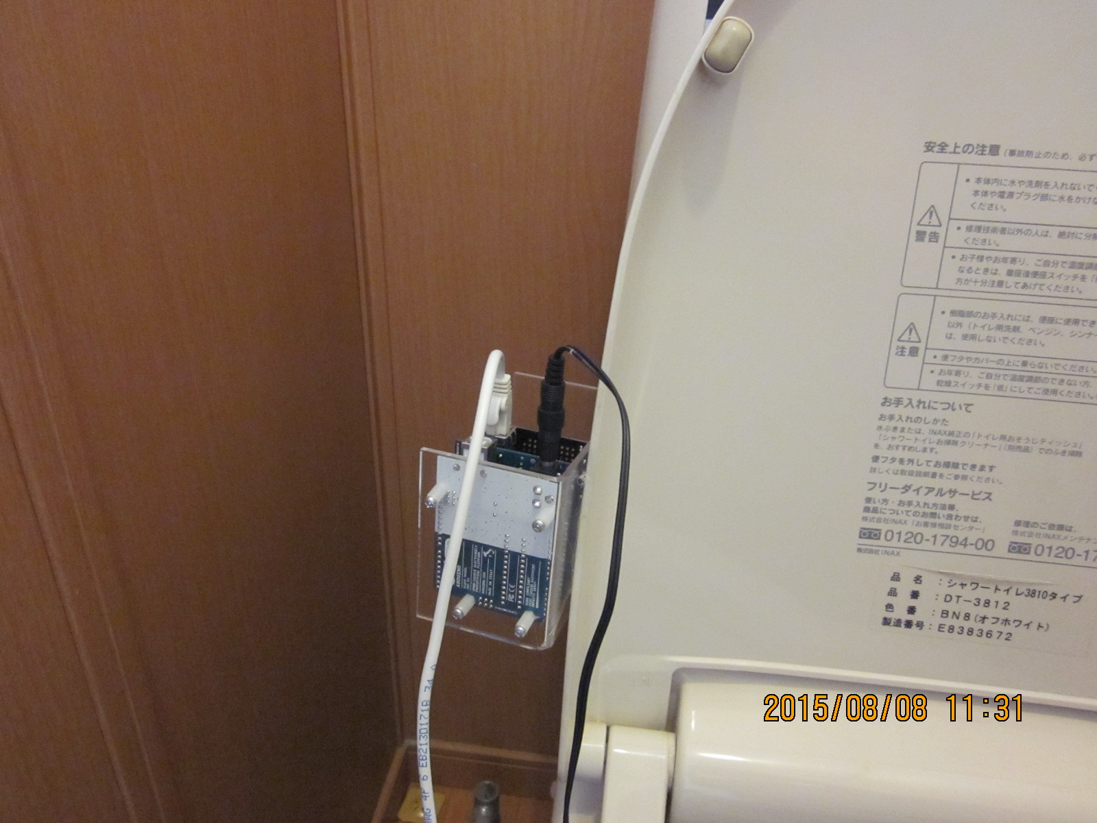
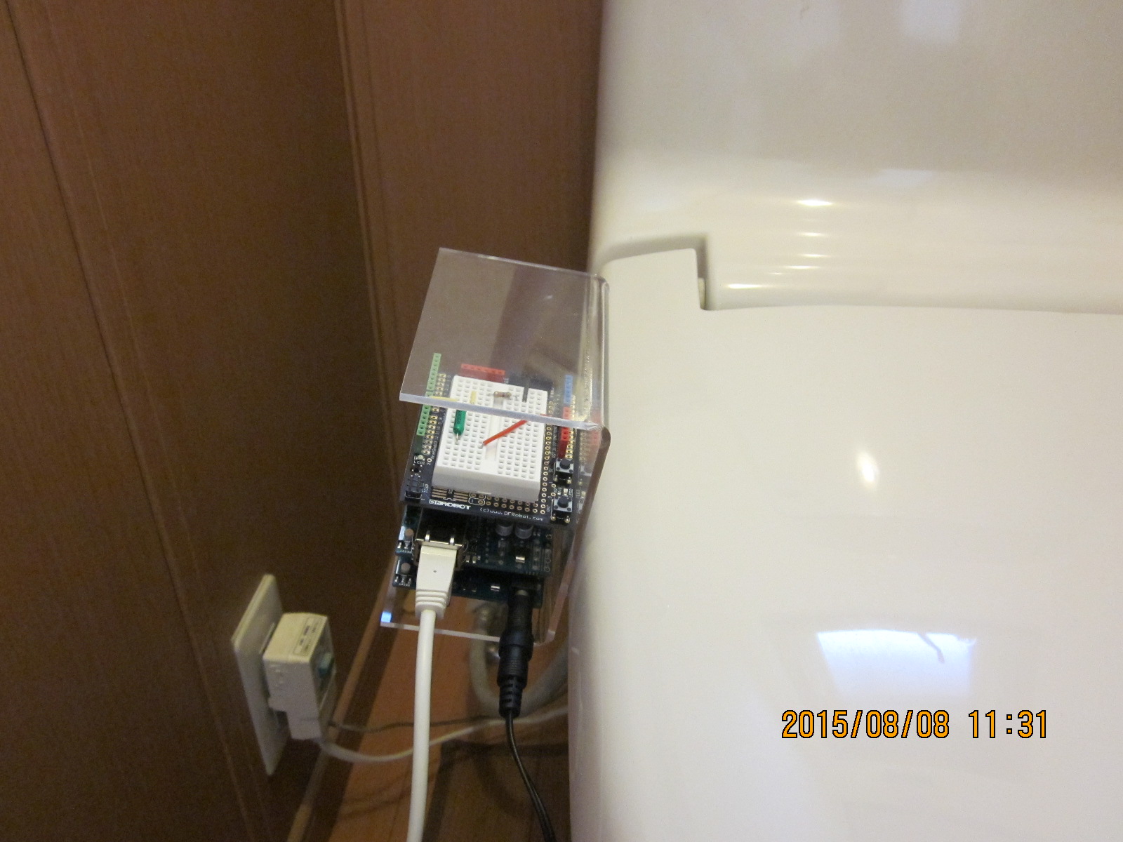
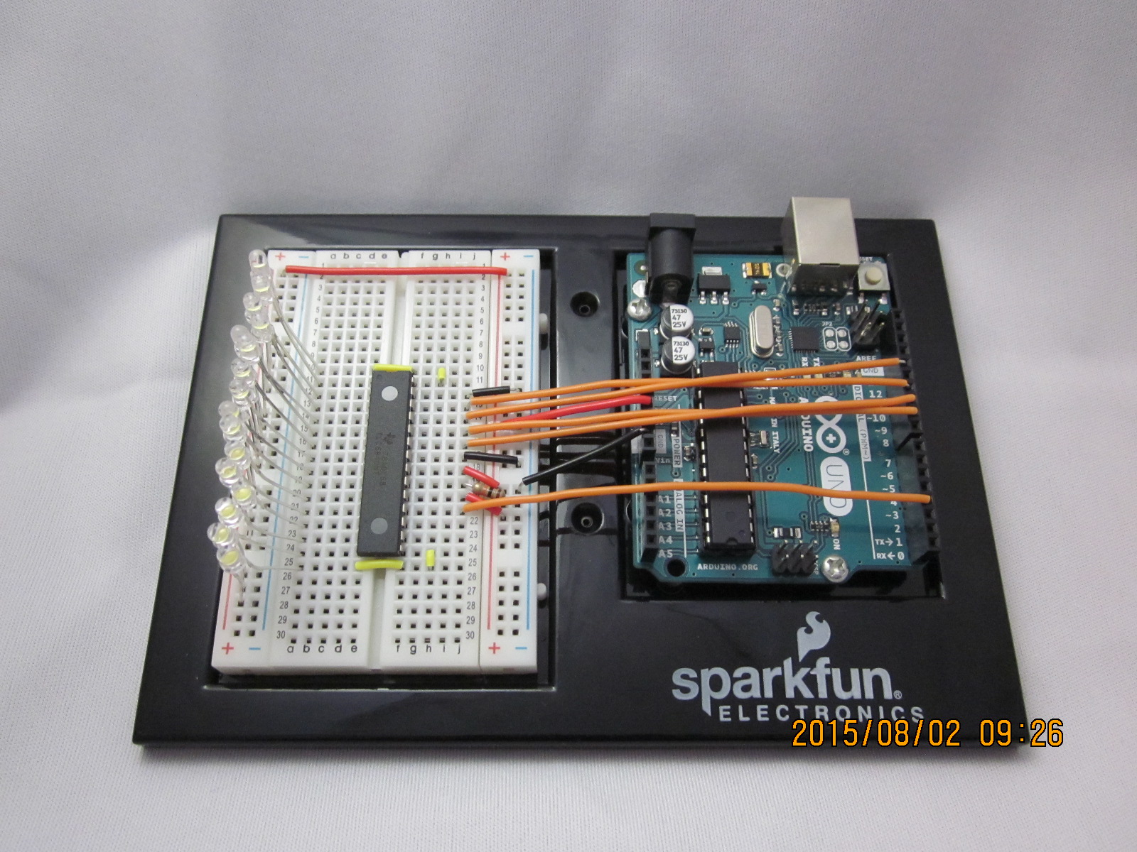
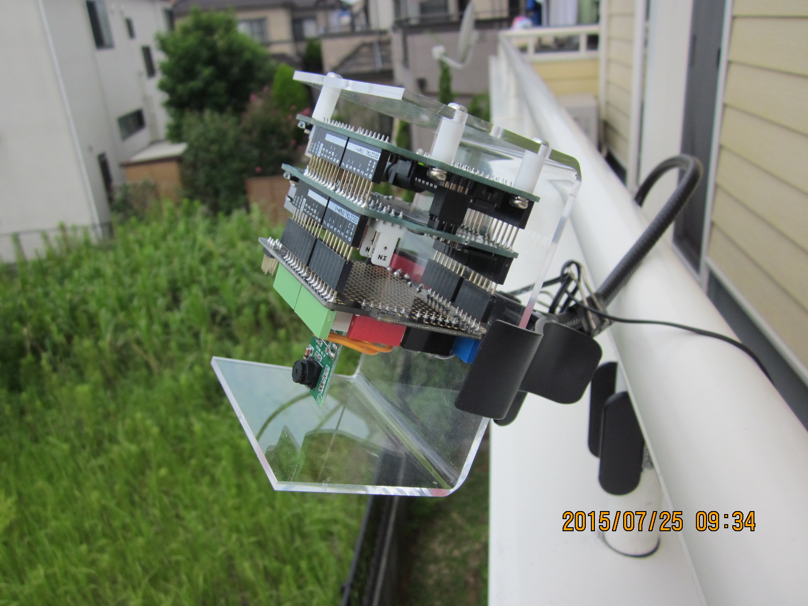
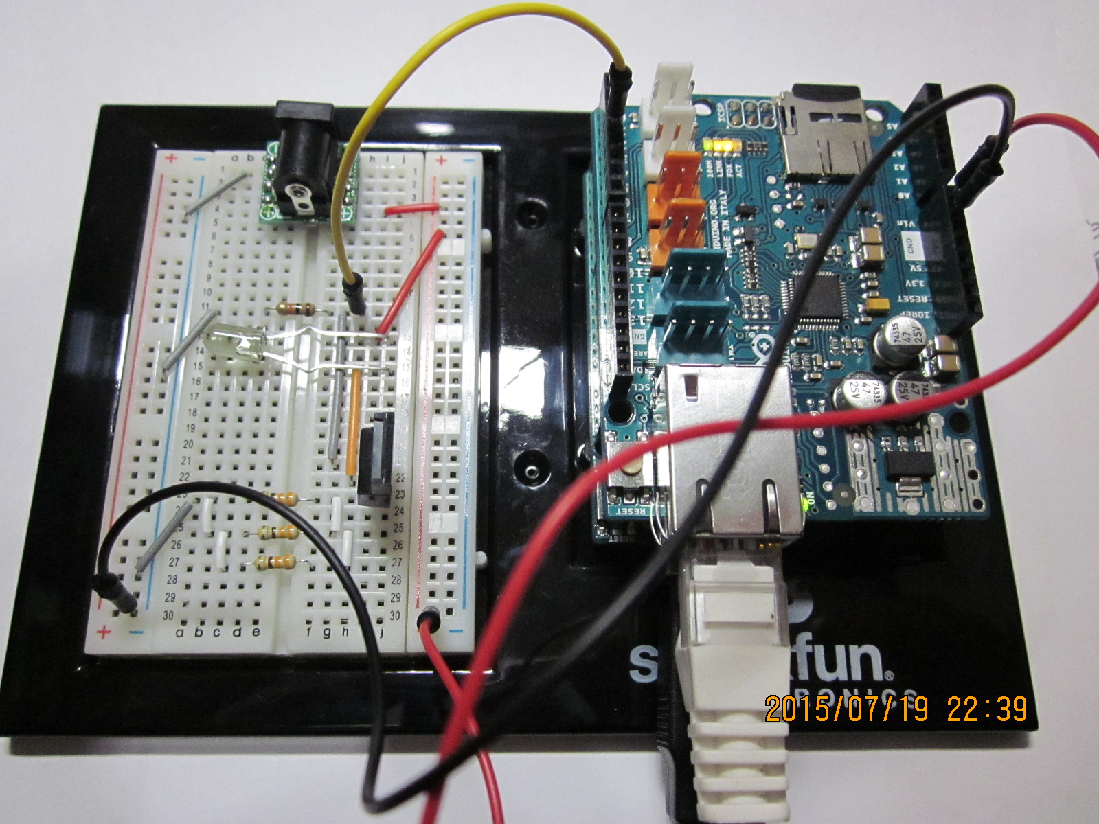
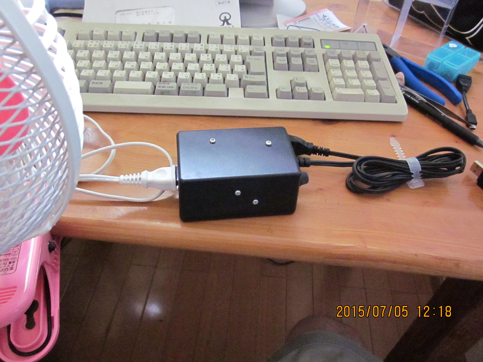
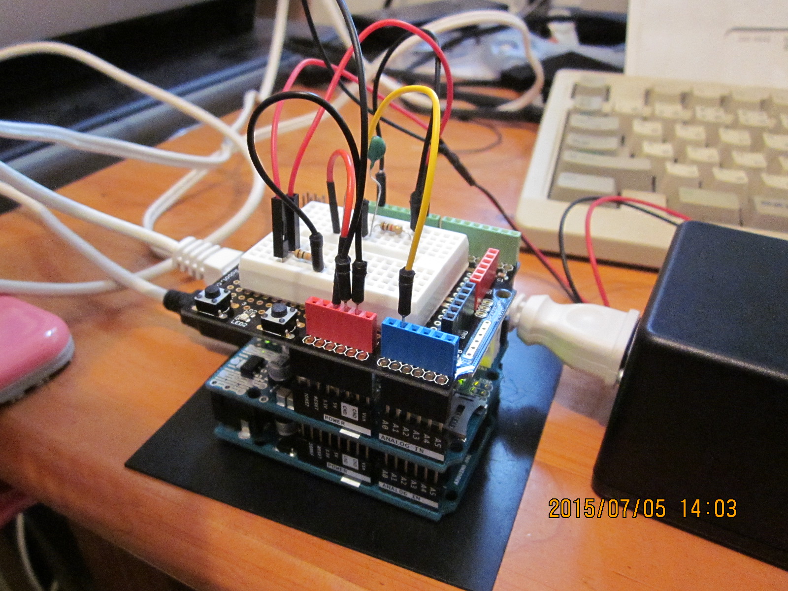
 ETHERNET SHIELD 2を遺憾なく使う。SDカードを取り付けられるから、そこにHTMLを書き込んでおけばよい。FETをつけたブレッドボードと一緒に、買っておいたSparkfunの基盤に固定する。
SDカード内には、次のようなHTMLを置き、ファイル名を「irform.htm」とする。
<html>
 <head>
  <meta name="Editor" content="Notepad.exe">
  <meta http-equiv="Content-Type" content="text/html;charset=Shift_JIS">
  <title>Webリモコン</title>
  <basefont size=4>
 </head>

 <body bgcolor="#ddffdd">
  <center>
   <h1><b>Webリモコン</b></h1>
     <table>
      <tr><td> 作成者   </td>
       <td align="right">佐藤俊夫</td></tr>
      <tr><td> 作成日時 </td>
       <td align="right">27.07.19 (日) 1835</td></tr>
     </table>
  </center>
  <hr>
  <center>
    <form method="get" name="irremote">
    <table border=1>
      <tr><th>機器</th><th>ボタン</th></tr>
      <tr>
        <td rowspan=4>扇風機</td>
        <td><input submit type="submit" value="入/風量" name="fan_on"></td>
      </tr>
        <tr><td><input submit type="submit" value="タイマー" name="fan_timer"></td></tr>
        <tr><td><input submit type="submit" value="首振" name="fan_swing"></td></tr>
        <tr><td><input submit type="submit" value="切" name="fan_off"></td></tr>
      </tr>
      <tr>
        <td rowspan=5>テレビ</td>
        <td><input submit type="submit" value="入/切" name="tv_on_off"></td>
      </tr>
        <tr><td><input submit type="submit" value="音量大" name="tv_volup"></td></tr>
        <tr><td><input submit type="submit" value="音量小" name="tv_voldown"></td></tr>
        <tr><td><input submit type="submit" value="チャンネル>" name="tv_chup"></td></tr>
        <tr><td><input submit type="submit" value="チャンネル<" name="tv_chdown"></td></tr>
    </table>
    </form>
  </center>
 </body>
</html>
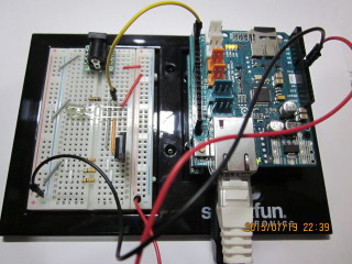
 上のHTMLの見た目はこんな感じだ。
スケッチは次のようになる。
//
//  Web2IRremote.ino
//    リモコンをウェブで操作する。
//    27.07.25(日) 1930
//    佐藤俊夫
//
#include <SPI.h>
#include <Ethernet2.h>
#include <SD.h>
#include <IRremote.h>
#include <avr/pgmspace.h>
//
byte mac[] = {  0x90, 0xA2, 0xDA, 0x0F, 0xF6, 0x74 };
IPAddress ip(192, 168, 1, 129);
EthernetServer SERVER(80);
EthernetClient CLIENT;
IRsend irsend;
PROGMEM
  const unsigned int
    fan_on[]     = {4500,2150, 600,500, 650,500, 600,500, 600,500, 600,1650, 600,1600, 650,1550, 650,500, 600,1600, 650,1600, 600,1600, 650,450, 600,1600, 650,500, 600,500, 650,500, 600,1600, 600,500, 650,500, 600,500, 600,500, 600,500, 600,1650, 600,500, 600,500, 600,500, 650,1600, 600,1600, 600,1650, 600,1600, 600,500, 650,500, 600,0},
    fan_timer[]  = {4500,2150, 550,550, 550,600, 550,550, 600,500, 550,1700, 500,1700, 550,1650, 550,600, 550,1650, 550,1700, 500,1700, 550,600, 500,1700, 550,550, 550,550, 550,600, 500,1700, 550,600, 500,600, 500,600, 500,600, 550,550, 550,1700, 550,600, 450,600, 550,550, 550,600, 500,1700, 550,1650, 550,1700, 550,1650, 550,600, 500,0},
    fan_swing[]  = {4450,2200, 600,550, 550,500, 600,550, 550,550, 550,1700, 550,1650, 550,1700, 550,550, 550,1650, 550,1700, 550,1650, 550,550, 600,1650, 550,550, 550,550, 550,550, 600,1650, 550,550, 550,550, 600,550, 550,550, 550,550, 600,1600, 600,550, 550,550, 550,1650, 600,1550, 650,1700, 550,1650, 550,550, 550,550, 600,550, 550,0},
    fan_off[]    = {4450,2250, 550,550, 600,550, 550,500, 600,550, 550,1650, 600,1650, 550,1650, 600,550, 550,1650, 550,1650, 600,1650, 550,550, 550,1700, 550,550, 550,550, 550,550, 550,1700, 550,550, 550,550, 550,550, 600,550, 550,550, 550,1650, 550,550, 600,550, 550,1650, 600,1650, 550,550, 550,1700, 550,500, 600,550, 550,1650, 600,0},
    tv_on_off[]  = {3400,1750, 400,500, 350,1350, 400,500, 350,500, 400,500, 350,500, 400,500, 350,450, 400,500, 400,500, 350,500, 400,500, 350,500, 350,1350, 400,500, 400,500, 350,450, 400,500, 400,500, 350,450, 400,500, 400,500, 350,500, 400,1300, 400,500, 400,450, 400,500, 400,500, 350,500, 350,500, 400,450, 400,450, 400,1350, 400,500, 400,1300, 400,1350, 400,1350, 400,1350, 400,450, 400,500, 400,1300, 400,500, 400,1300, 400,1350, 400,1350, 400,1350, 400,500, 350,1350, 400,0},
    tv_volup[]   = {3400,1750, 400,500, 400,1300, 400,500, 400,500, 350,500, 450,400, 400,500, 350,500, 400,500, 350,500, 350,500, 400,500, 350,500, 400,1300, 400,500, 400,450, 400,500, 350,500, 400,500, 350,500, 400,500, 350,500, 350,500, 400,1300, 450,450, 400,500, 350,500, 400,500, 350,500, 400,450, 400,500, 350,500, 400,500, 350,450, 400,500, 400,500, 350,500, 450,1250, 400,500, 400,500, 350,500, 400,450, 400,500, 350,500, 400,500, 350,1350, 400,450, 400,1350, 400,0},
    tv_voldown[] = {3400,1750, 400,500, 350,1350, 400,500, 400,450, 400,500, 350,500, 400,450, 400,500, 400,500, 350,500, 350,500, 400,500, 350,500, 350,1300, 450,500, 400,500, 350,450, 400,500, 450,450, 350,500, 400,450, 400,450, 400,500, 400,1300, 450,500, 350,500, 350,500, 400,500, 350,450, 400,500, 400,500, 350,500, 400,1300, 400,500, 400,450, 400,500, 400,500, 350,1350, 400,500, 350,500, 400,1300, 400,500, 400,500, 350,500, 350,500, 400,1300, 450,500, 350,1350, 400,0},
    tv_chup[]    = {3400,1750, 400,500, 400,1350, 450,400, 400,450, 400,500, 450,400, 400,450, 400,500, 450,450, 450,400, 450,450, 400,400, 400,500, 450,1250, 450,500, 350,450, 500,400, 450,400, 400,500, 350,500, 450,450, 350,500, 450,450, 450,1250, 400,500, 450,400, 400,500, 400,450, 450,400, 450,450, 350,500, 450,400, 450,450, 350,500, 450,1250, 400,500, 450,1250, 500,1250, 500,400, 450,450, 350,500, 450,450, 350,1350, 450,450, 400,1300, 450,1250, 500,450, 400,1250, 450,0},
    tv_chdown[]  = {3500,1650, 450,500, 400,1300, 400,500, 450,400, 350,500, 400,450, 500,400, 450,450, 350,450, 400,500, 400,500, 350,500, 400,450, 450,1300, 450,450, 350,450, 450,500, 350,500, 450,400, 450,400, 400,500, 350,500, 450,400, 400,1350, 450,400, 500,400, 450,450, 450,400, 400,500, 350,500, 350,500, 400,500, 350,1350, 450,450, 350,1350, 400,500, 350,1350, 500,1250, 450,450, 450,400, 450,1250, 500,400, 450,1300, 450,450, 400,1300, 450,1250, 450,500, 350,1350, 450,0};
////
void setup()
{
  const int chipSelect = 4;
  Ethernet.begin(mac, ip);
  SERVER.begin();
  if (!SD.begin(chipSelect)) {
    return;
  }
}

void loop()
{
  //  Webサーバの動作
  char c;
  String rstr = "";
  CLIENT = SERVER.available();
  if (CLIENT) {
    while (CLIENT.connected()) {
      if (CLIENT.available()) {
        c = CLIENT.read();
        rstr += c;
        if(rstr.endsWith("\r\n")){
          break;
        }
      }
    }
    if(rstr.indexOf("fan_on=") >= 0){
      unsigned int buf[sizeof(fan_on) / sizeof(*fan_on)];
      for(int i = 0; i < sizeof(fan_on) / sizeof(*fan_on); i++){
        buf[i] = pgm_read_word(fan_on + i);
      }
      irsend.sendRaw(buf, sizeof(buf) / sizeof(buf[0]), 38);
    }
    else if(rstr.indexOf("fan_timer=") >= 0){
      unsigned int buf[sizeof(fan_timer) / sizeof(*fan_timer)];
      for(int i = 0; i < sizeof(fan_timer) / sizeof(*fan_timer); i++){
        buf[i] = pgm_read_word(fan_timer + i);
      }
      irsend.sendRaw(buf, sizeof(buf) / sizeof(buf[0]), 38);
    }
    else if(rstr.indexOf("fan_swing=") >= 0){
      unsigned int buf[sizeof(fan_swing) / sizeof(*fan_swing)];
      for(int i = 0; i < sizeof(fan_swing) / sizeof(*fan_swing); i++){
        buf[i] = pgm_read_word(fan_swing + i);
      }
      irsend.sendRaw(buf, sizeof(buf) / sizeof(buf[0]), 38);
    }
    else if(rstr.indexOf("fan_off=") >= 0){
     unsigned int buf[sizeof(fan_off) / sizeof(*fan_off)];
     for(int i = 0; i < sizeof(fan_off) / sizeof(*fan_off); i++){
        buf[i] = pgm_read_word(fan_off + i);
      }
      irsend.sendRaw(buf, sizeof(buf) / sizeof(buf[0]), 38);
    }
    else if(rstr.indexOf("tv_on_off=") >= 0){
     unsigned int buf[sizeof(tv_on_off) / sizeof(*tv_on_off)];
     for(int i = 0; i < sizeof(tv_on_off) / sizeof(*tv_on_off); i++){
        buf[i] = pgm_read_word(tv_on_off + i);
      }
      irsend.sendRaw(buf, sizeof(buf) / sizeof(buf[0]), 38);
    }
    else if(rstr.indexOf("tv_volup=") >= 0){
     unsigned int buf[sizeof(tv_volup) / sizeof(*tv_volup)];
     for(int i = 0; i < sizeof(tv_volup) / sizeof(*tv_volup); i++){
        buf[i] = pgm_read_word(tv_volup + i);
      }
      irsend.sendRaw(buf, sizeof(buf) / sizeof(buf[0]), 38);
    }
    else if(rstr.indexOf("tv_voldown=") >= 0){
     unsigned int buf[sizeof(tv_voldown) / sizeof(*tv_voldown)];
     for(int i = 0; i < sizeof(tv_voldown) / sizeof(*tv_voldown); i++){
        buf[i] = pgm_read_word(tv_voldown + i);
      }
      irsend.sendRaw(buf, sizeof(buf) / sizeof(buf[0]), 38);
    }
    else if(rstr.indexOf("tv_chup=") >= 0){
     unsigned int buf[sizeof(tv_chup) / sizeof(*tv_chup)];
     for(int i = 0; i < sizeof(tv_chup) / sizeof(*tv_chup); i++){
        buf[i] = pgm_read_word(tv_chup + i);
      }
      irsend.sendRaw(buf, sizeof(buf) / sizeof(buf[0]), 38);
    }
    else if(rstr.indexOf("tv_chdown=") >= 0){
     unsigned int buf[sizeof(tv_chdown) / sizeof(*tv_chdown)];
     for(int i = 0; i < sizeof(tv_chdown) / sizeof(*tv_chdown); i++){
        buf[i] = pgm_read_word(tv_chdown + i);
      }
      irsend.sendRaw(buf, sizeof(buf) / sizeof(buf[0]), 38);
    }
    rstr = "";
    sendform();
    delay(1);
    // close the connection:
    CLIENT.stop();
  }
  delay(20);
}
void sendform(){
  //  フォームを送る。
  CLIENT.println("HTTP/1.1 200 OK");
  CLIENT.println("Content-Type: text/html");
  CLIENT.println("Connection: close");
  CLIENT.println();
  CLIENT.println("<!DOCTYPE HTML>");
  File html = SD.open("irform.htm");
  if (html) {
    while (html.available()) {
      CLIENT.write(html.read());
    }
    html.close();
  }
}
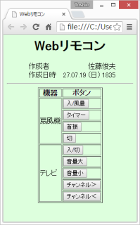
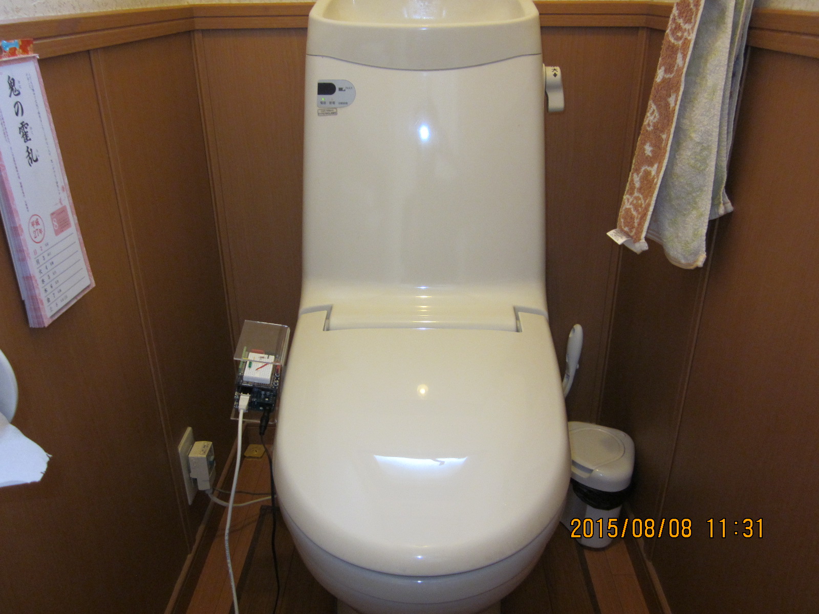
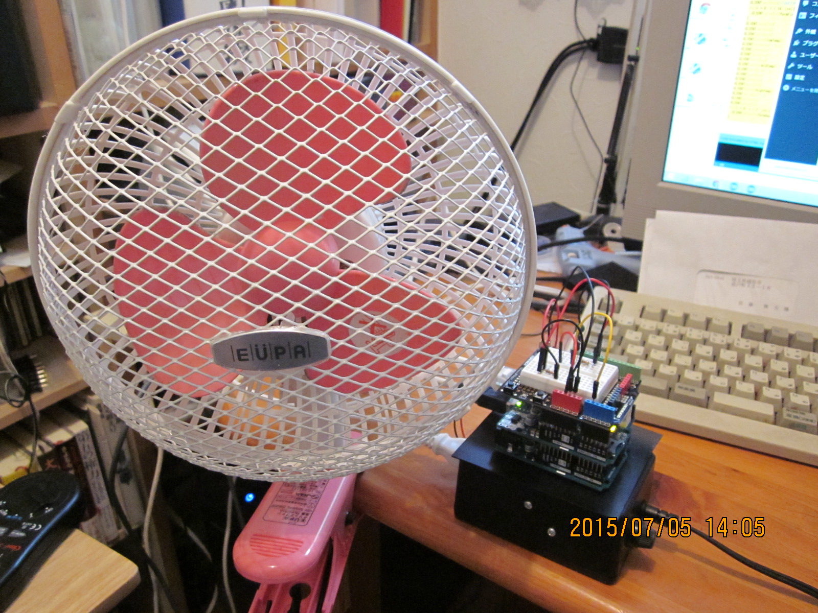
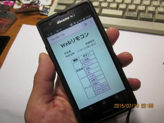 勿論、ただのWebであるから、このようにスマホの他、タブレットなどからも操作可能である。また、ルータでポートフォワードすれば、外出先からの操作も可能である。


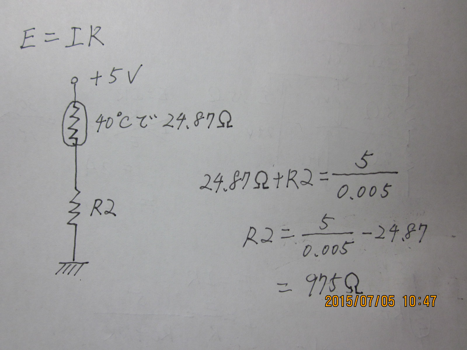
 という、この式のみでよい。LEDを買ってくると、流すべき電流値(If)、光り始める電圧(Vf)がどこかに書いてあるから、それに従って計算する。すなわち、

 …①
…① …②
…②


 として
として のとき
のとき
 のとき
のとき