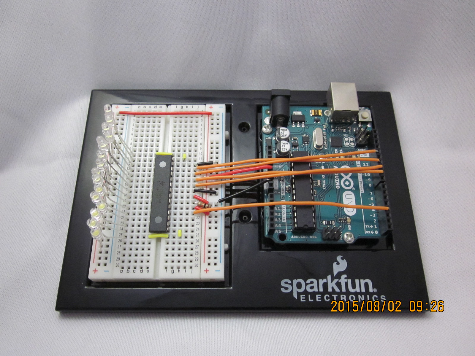
/* Basic Pin setup: ------------ ---u---- ARDUINO 13|-> SCLK (pin 25) OUT1 |1 28| OUT channel 0 12| OUT2 |2 27|-> GND (VPRG) 11|-> SIN (pin 26) OUT3 |3 26|-> SIN (pin 11) 10|-> BLANK (pin 23) OUT4 |4 25|-> SCLK (pin 13) 9|-> XLAT (pin 24) . |5 24|-> XLAT (pin 9) 8| . |6 23|-> BLANK (pin 10) 7| . |7 22|-> GND 6| . |8 21|-> VCC (+5V) 5| . |9 20|-> 2K Resistor -> GND 4| . |10 19|-> +5V (DCPRG) 3|-> GSCLK (pin 18) . |11 18|-> GSCLK (pin 3) 2| . |12 17|-> SOUT 1| . |13 16|-> XERR 0| OUT14|14 15| OUT channel 15 ------------ -------- - Put the longer leg (anode) of the LEDs in the +5V and the shorter leg (cathode) in OUT(0-15). - +5V from Arduino -> TLC pin 21 and 19 (VCC and DCPRG) - GND from Arduino -> TLC pin 22 and 27 (GND and VPRG) - digital 3 -> TLC pin 18 (GSCLK) - digital 9 -> TLC pin 24 (XLAT) - digital 10 -> TLC pin 23 (BLANK) - digital 11 -> TLC pin 26 (SIN) - digital 13 -> TLC pin 25 (SCLK) - The 2K resistor between TLC pin 20 and GND will let ~20mA through each LED. To be precise, it's I = 39.06 / R (in ohms). This doesn't depend on the LED driving voltage. - (Optional): put a pull-up resistor (~10k) between +5V and BLANK so that all the LEDs will turn off when the Arduino is reset. If you are daisy-chaining more than one TLC, connect the SOUT of the first TLC to the SIN of the next. All the other pins should just be connected together: BLANK on Arduino -> BLANK of TLC1 -> BLANK of TLC2 -> ... XLAT on Arduino -> XLAT of TLC1 -> XLAT of TLC2 -> ... The one exception is that each TLC needs it's own resistor between pin 20 and GND. This library uses the PWM output ability of digital pins 3, 9, 10, and 11. Do not use analogWrite(...) on these pins. This sketch does the Knight Rider strobe across a line of LEDs. Alex Leone <acleone ~AT~ gmail.com>, 2009-02-03 */
#include "Tlc5940.h"voidsetup()
{
/* Call Tlc.init() to setup the tlc. You can optionally pass an initial PWM value (0 - 4095) for all channels.*/
Tlc.init();
}
/* This loop will create a Knight Rider-like effect if you have LEDs plugged into all the TLC outputs. NUM_TLCS is defined in "tlc_config.h" in the library folder. After editing tlc_config.h for your setup, delete the Tlc5940.o file to save the changes. */voidloop()
{
intdirection = 1;
for (int channel = 0; channel < NUM_TLCS * 16; channel += direction) {
/* Tlc.clear() sets all the grayscale values to zero, but does not send them to the TLCs. To actually send the data, call Tlc.update() */
Tlc.clear();
/* Tlc.set(channel (0-15), value (0-4095)) sets the grayscale value for one channel (15 is OUT15 on the first TLC, if multiple TLCs are daisy- chained, then channel = 16 would be OUT0 of the second TLC, etc.). value goes from off (0) to always on (4095). Like Tlc.clear(), this function only sets up the data, Tlc.update() will send the data. */if (channel == 0) {
direction = 1;
} else {
Tlc.set(channel - 1, 1000);
}
Tlc.set(channel, 4095);
if (channel != NUM_TLCS * 16 - 1) {
Tlc.set(channel + 1, 1000);
} else {
direction = -1;
}
/* Tlc.update() sends the data to the TLCs. This is when the LEDs will actually change. */
Tlc.update();
delay(75);
}
}
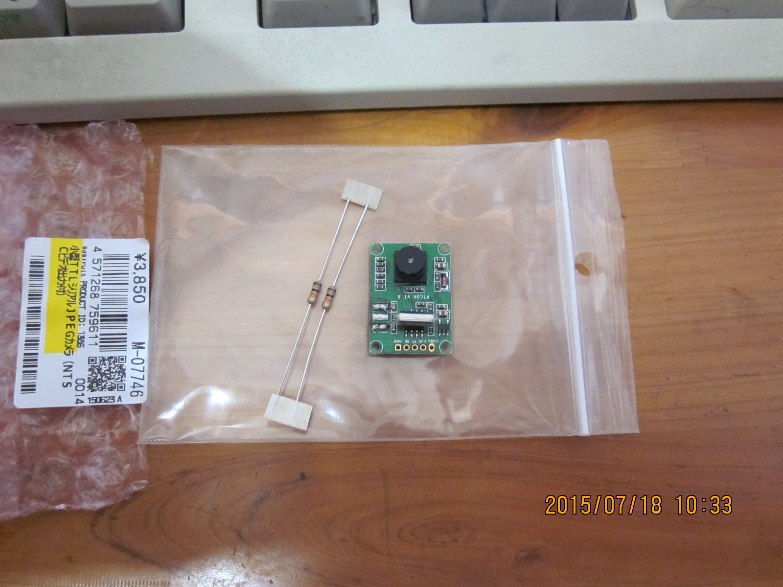
そうしておいてArduinoのIDEを起動すると、「ファイル」→「スケッチの例」の中に「Adafruit VC0706 Serial Camera Library」が現れるから、この中から「Snapshot」を選ぶ。これは静止画をjpegで撮影するスケッチのサンプルだ。
// This is a basic snapshot sketch using the VC0706 library.// On start, the Arduino will find the camera and SD card and// then snap a photo, saving it to the SD card.// Public domain.// If using an Arduino Mega (1280, 2560 or ADK) in conjunction// with an SD card shield designed for conventional Arduinos// (Uno, etc.), it's necessary to edit the library file:// libraries/SD/utility/Sd2Card.h// Look for this line:// #define MEGA_SOFT_SPI 0// change to:// #define MEGA_SOFT_SPI 1// This is NOT required if using an SD card breakout interfaced// directly to the SPI bus of the Mega (pins 50-53), or if using// a non-Mega, Uno-style board.
#include <Adafruit_VC0706.h>
#include <SPI.h>
#include <SD.h>
// comment out this line if using Arduino V23 or earlier
#include <SoftwareSerial.h>
// uncomment this line if using Arduino V23 or earlier// #include <NewSoftSerial.h> // SD card chip select line varies among boards/shields:// Adafruit SD shields and modules: pin 10// Arduino Ethernet shield: pin 4// Sparkfun SD shield: pin 8// Arduino Mega w/hardware SPI: pin 53// Teensy 2.0: pin 0// Teensy++ 2.0: pin 20
#define chipSelect 10
// Pins for camera connection are configurable.// With the Arduino Uno, etc., most pins can be used, except for// those already in use for the SD card (10 through 13 plus// chipSelect, if other than pin 10).// With the Arduino Mega, the choices are a bit more involved:// 1) You can still use SoftwareSerial and connect the camera to// a variety of pins...BUT the selection is limited. The TX// pin from the camera (RX on the Arduino, and the first// argument to SoftwareSerial()) MUST be one of: 62, 63, 64,// 65, 66, 67, 68, or 69. If MEGA_SOFT_SPI is set (and using// a conventional Arduino SD shield), pins 50, 51, 52 and 53// are also available. The RX pin from the camera (TX on// Arduino, second argument to SoftwareSerial()) can be any// pin, again excepting those used by the SD card.// 2) You can use any of the additional three hardware UARTs on// the Mega board (labeled as RX1/TX1, RX2/TX2, RX3,TX3),// but must specifically use the two pins defined by that// UART; they are not configurable. In this case, pass the// desired Serial object (rather than a SoftwareSerial// object) to the VC0706 constructor.// Using SoftwareSerial (Arduino 1.0+) or NewSoftSerial (Arduino 0023 & prior):
#if ARDUINO >= 100
// On Uno: camera TX connected to pin 2, camera RX to pin 3:SoftwareSerial cameraconnection = SoftwareSerial(2, 3);
// On Mega: camera TX connected to pin 69 (A15), camera RX to pin 3://SoftwareSerial cameraconnection = SoftwareSerial(69, 3);
#else
NewSoftSerial cameraconnection = NewSoftSerial(2, 3);
#endif
Adafruit_VC0706 cam = Adafruit_VC0706(&cameraconnection);
// Using hardware serial on Mega: camera TX conn. to RX1,// camera RX to TX1, no SoftwareSerial object is required://Adafruit_VC0706 cam = Adafruit_VC0706(&Serial1);voidsetup() {
// When using hardware SPI, the SS pin MUST be set to an// output (even if not connected or used). If left as a// floating input w/SPI on, this can cause lockuppage.
#if !defined(SOFTWARE_SPI)
#if defined(__AVR_ATmega1280__) || defined(__AVR_ATmega2560__)
if(chipSelect != 53) pinMode(53, OUTPUT); // SS on Mega
#else
if(chipSelect != 10) pinMode(10, OUTPUT); // SS on Uno, etc.
#endif
#endif
Serial.begin(9600);
Serial.println("VC0706 Camera snapshot test");
// see if the card is present and can be initialized:if (!SD.begin(chipSelect)) {
Serial.println("Card failed, or not present");
// don't do anything more:return;
}
// Try to locate the cameraif (cam.begin()) {
Serial.println("Camera Found:");
} else {
Serial.println("No camera found?");
return;
}
// Print out the camera version information (optional)char *reply = cam.getVersion();
if (reply == 0) {
Serial.print("Failed to get version");
} else {
Serial.println("-----------------");
Serial.print(reply);
Serial.println("-----------------");
}
// Set the picture size - you can choose one of 640x480, 320x240 or 160x120 // Remember that bigger pictures take longer to transmit!
cam.setImageSize(VC0706_640x480); // biggest//cam.setImageSize(VC0706_320x240); // medium//cam.setImageSize(VC0706_160x120); // small// You can read the size back from the camera (optional, but maybe useful?)
uint8_t imgsize = cam.getImageSize();
Serial.print("Image size: ");
if (imgsize == VC0706_640x480) Serial.println("640x480");
if (imgsize == VC0706_320x240) Serial.println("320x240");
if (imgsize == VC0706_160x120) Serial.println("160x120");
Serial.println("Snap in 3 secs...");
delay(3000);
if (! cam.takePicture())
Serial.println("Failed to snap!");
elseSerial.println("Picture taken!");
// Create an image with the name IMAGExx.JPGchar filename[13];
strcpy(filename, "IMAGE00.JPG");
for (int i = 0; i < 100; i++) {
filename[5] = '0' + i/10;
filename[6] = '0' + i%10;
// create if does not exist, do not open existing, write, sync after writeif (! SD.exists(filename)) {
break;
}
}
// Open the file for writingFile imgFile = SD.open(filename, FILE_WRITE);
// Get the size of the image (frame) taken
uint16_t jpglen = cam.frameLength();
Serial.print("Storing ");
Serial.print(jpglen, DEC);
Serial.print(" byte image.");
int32_t time = millis();
pinMode(8, OUTPUT);
// Read all the data up to # bytes!byte wCount = 0; // For counting # of writeswhile (jpglen > 0) {
// read 32 bytes at a time;
uint8_t *buffer;
uint8_t bytesToRead = min(32, jpglen); // change 32 to 64 for a speedup but may not work with all setups!buffer = cam.readPicture(bytesToRead);
imgFile.write(buffer, bytesToRead);
if(++wCount >= 64) { // Every 2K, give a little feedback so it doesn't appear locked upSerial.print('.');
wCount = 0;
}
//Serial.print("Read "); Serial.print(bytesToRead, DEC); Serial.println(" bytes");
jpglen -= bytesToRead;
}
imgFile.close();
time = millis() - time;
Serial.println("done!");
Serial.print(time); Serial.println(" ms elapsed");
}
voidloop() {
}

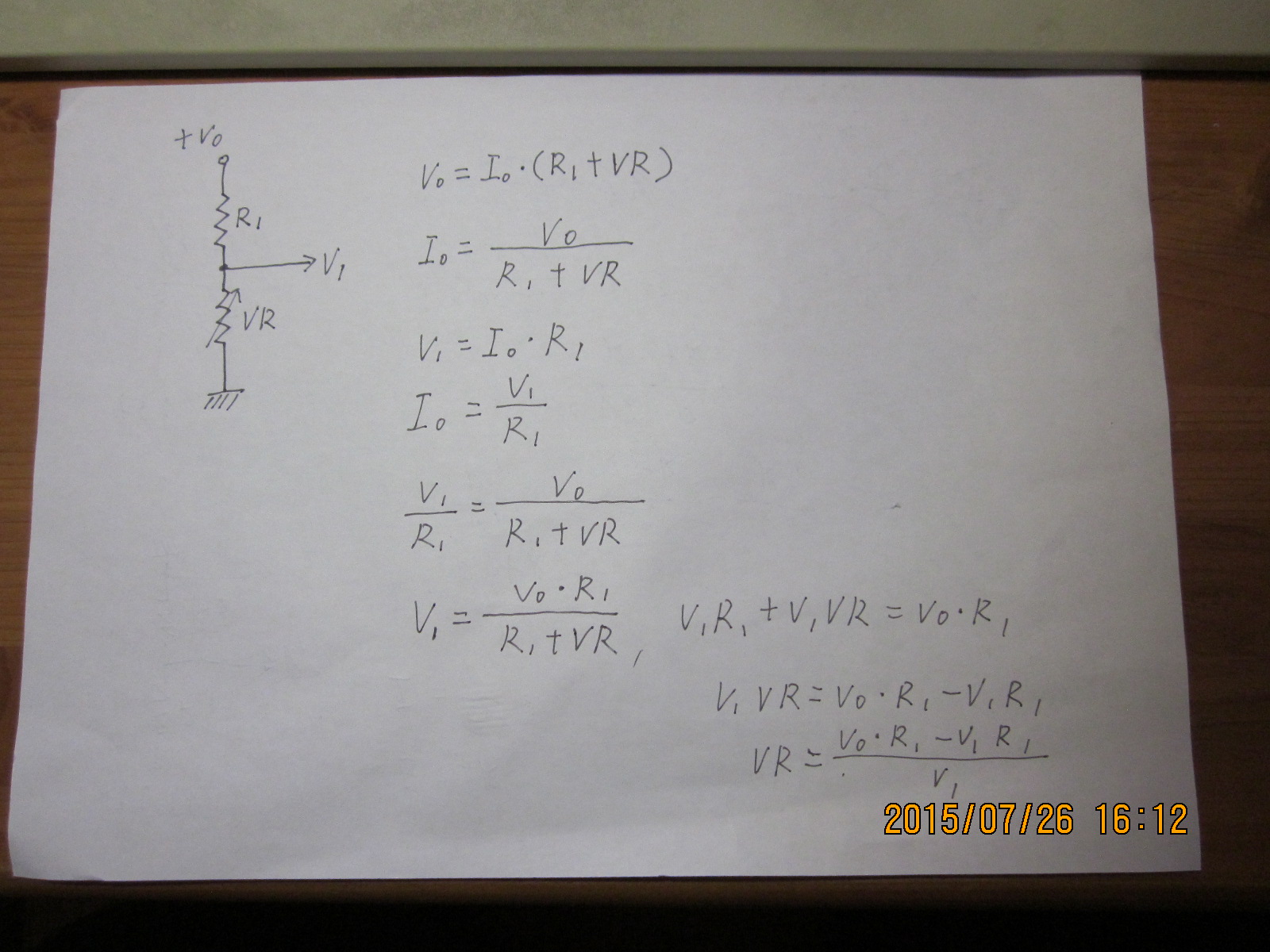
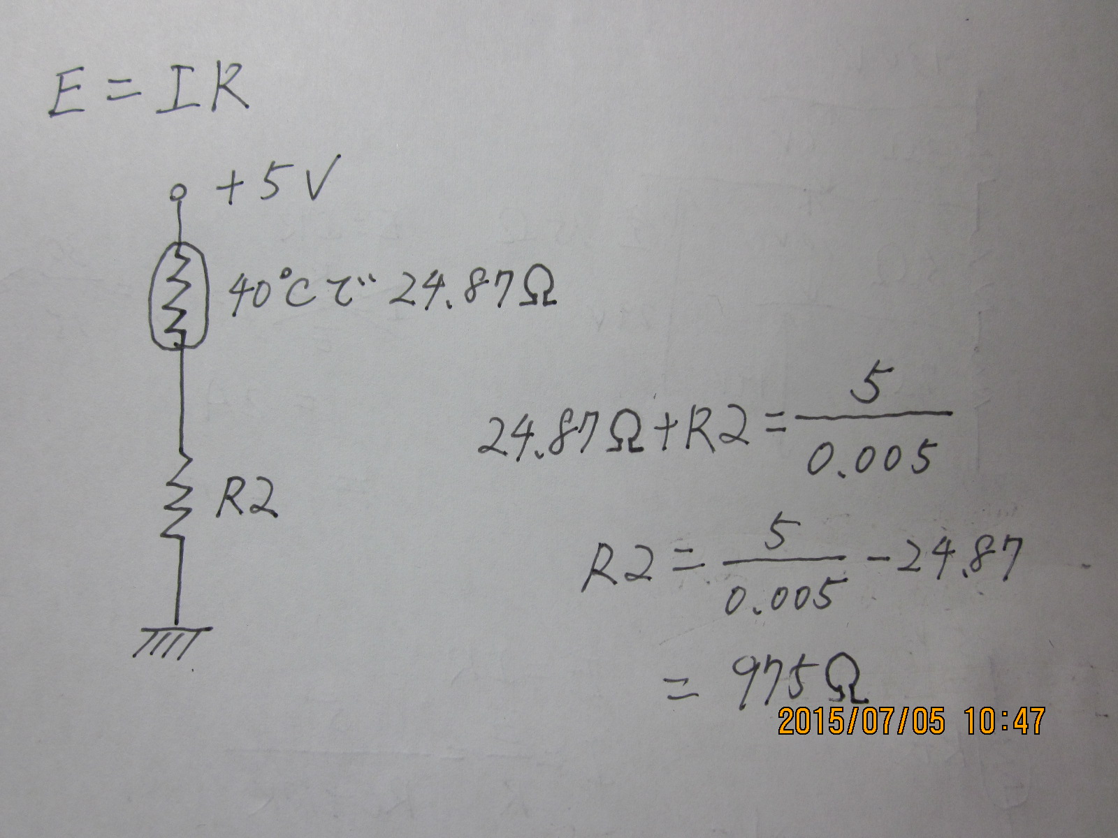
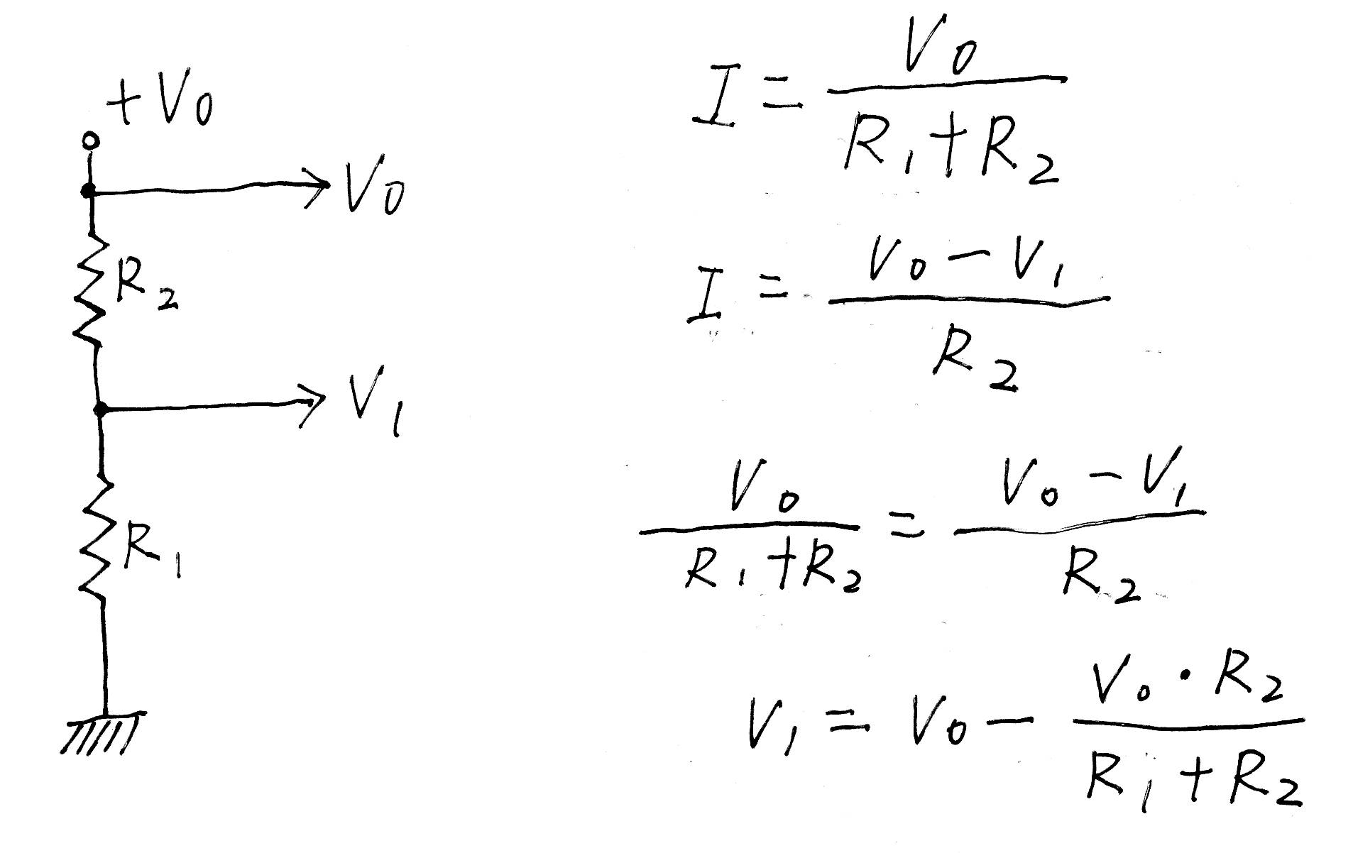
 という、この式のみでよい。LEDを買ってくると、流すべき電流値(If)、光り始める電圧(Vf)がどこかに書いてあるから、それに従って計算する。すなわち、

 …①
…① …②
…②